Using UV LEDs to Cure Fiber Optic Cables
Modern fiber optics have undergone remarkable advances since their development in the 1960s. The growing demand for fiber-optic cable, especially in the telecommunications industry, has led to an increase in high-volume production of optical fiber. New high-irradiance UV LED curing systems widely deployed in the last decade for the assembly of electronics, optics, and medical devices are now being utilized by fiber-optics manufacturers as a complement or an alternative to current technology to help meet the increasing demand. At the same time, the high efficiency, long lifetime, and low cost of operation of UV LED curing systems will significantly reduce the operational cost in this high-speed manufacturing process.
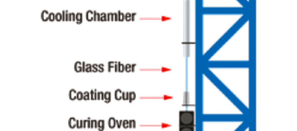
Glass optical fiber is produced on a multi-story drawing tower where, at the top, a preform is heated and pulled to a thin strand at speeds in excess of 3000m/min (Figure 1). To protect the glass fiber, two layers of coating material such as acrylate polymer or polyimide are applied to the fiber in concentric layers and then rapidly cured with high-intensity UV light.
In current fiber-optic manufacturing processes, high-intensity UV arc lamp or UV microwave excited lamp systems are used to cure the fiber coatings. These systems generate UV light by passing electric arcs or microwaves through a mercury and/or metal halide-filled glass tube, resulting in high-pressure mercury vapor. UV lamps produce a very wide spectral output from below 200 nm to above 800 nm, which is effective for curing current fiber optic coatings. However, these lamps suffer from a number of process disadvantages including high operational costs and frequent downtime.
UV energy from 250 nm to 420 nm is typically most effective in the curing of fiber optic coatings. UV lamps produce large amounts of energy in extraneous wavelengths outside this range, which do not contribute to the curing process, and therefore are wasted energy. UV lamps are also inherently inefficient in converting electrical energy into UV light, requiring significant electrical consumption to provide sufficient light energy for curing at speeds of over 3000m/min. Each UV lamp used in a fiber curing tower can use as much as 6kW of electrical power.
UV LED systems have the benefit of converting electrical energy into light energy much more efficiently, providing a significant reduction in electricity operating costs. A single UV LED curing system can use as little as 600W of electricity. Cost savings from the reduced electrical consumption alone can be enough to very quickly pay back the investment on the installation of the LED systems.
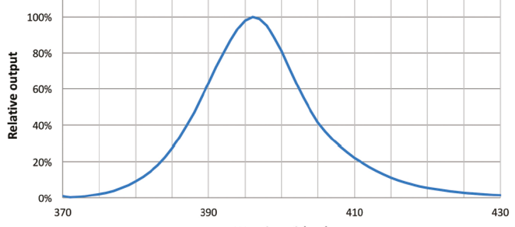
UV LED curing systems generate a much narrower spectrum of light at specific peak wavelengths, for example 365 nm or 395 nm, with a full width half maximum of only about 20 nm (Figure 2).
A benefit is that the full spectrum of energy produced by the LED is in the effective curing range of the fiber coatings. However, the narrow spectrum of the LED system may also create some challenges when curing fiber optic coatings that have been optimized for the broad spectrum of Hg lamps. It is therefore important to do specific material testing with the LED systems and work closely with the fiber coating supplier to ensure the required physical properties of the coating are achieved.
The UV arc lamps require replacement every 1,000 to 4,000 operating hours, while UV microwave excited lamps require replacement every 6,000 to 8,000 operating hours, adding to costs and process downtime. Other consumable items include the magnetron of UV microwave systems and reflectors which must be regularly cleaned and replaced. This again results in manufacturing downtime and additional cost in terms of parts and technical support.
High-output, air-cooled UV LED curing systems are straightforward to incorporate into a fiber drawing tower. The LED heads are also intrinsically long-lived and have innovative thermal designs with typical operational lifetimes of greater than 40,000 hours. UV LED systems use efficient and reliable constant-current drivers, which require no ballast or magnetron replacement, further reducing downtime and replacement costs compared to lamp-based systems.
The challenge with any UV curing system for fiber coating is to focus enough light energy onto the very small fiber in order to fully cure the coatings at speeds in excess of 3000m/min. The light must be focused at the specific working distance between the curing system and the fiber, typically from 10 to 18 mm. UV lamp systems will often incorporate external reflectors on the opposite side of the fiber in order to recycle the light energy, which does not initially hit the small target, to increase the efficiency of curing and achieve a uniform cure on all sides of the fiber.
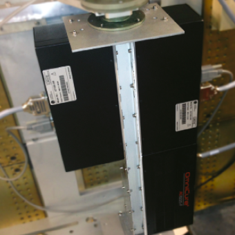
LED Systems arranged in a lens-to-lens configuration for fiber curing
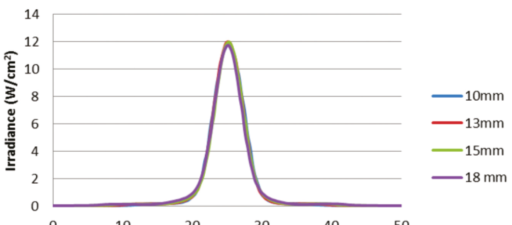
UV LED curing systems with advanced LED light-engine design and front-end optics are able to maximize the irradiance at the fiber. The customized lenses produce a highly focused beam (line) of light from the LED to optimize the curing efficiency by maximizing the UV energy onto the very thin strand of fiber. An inherent challenge with LED curing systems is to maintain the high irradiance over working distances due to the divergence of light from the LED source. Custom optics maintain the irradiance almost unchanged from 10 to 18 mm, the typical working distances for the fiber coating application
LED systems can be used in a number of configurations depending on the manufacturing process and coating material. One effective configuration involves arranging two LED systems, with focusing lenses facing each other, to achieve a uniform UV intensity at the fiber. Because UV LED systems may be arranged in a lens-to-lens configuration, no external reflector is required, which saves additional costs and downtime compared to lamp-based systems. The current UV lamps also require a higher infrastructure cost due to ozone production. Radiation of wavelengths less than 200 nm generates ozone from oxygen in the air. UV arc lamp systems which generate light below 200 nm produce ozone that must be filtered and vented to the outside with an exhaust system. Production facilities, which must conform to EN14001 requirements, include costly stacks and scrubbers. The narrow-spectrum UV LED curing systems do not produce light below 200 nm, and therefore do not generate ozone, eliminating the need for external venting. This further reduces operating costs and simplifies compliance with environmental standards.
Conclusion
New high-irradiance, air-cooled UV LED curing systems are being used to effectively complement or replace current UV lamp technology in the manufacturing of fiber optic cable. The high efficiency, long lifetime, and low electricity consumption of UV LED curing systems significantly reduce the operational cost in this high-speed manufacturing process.